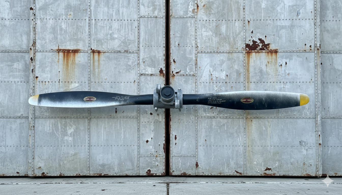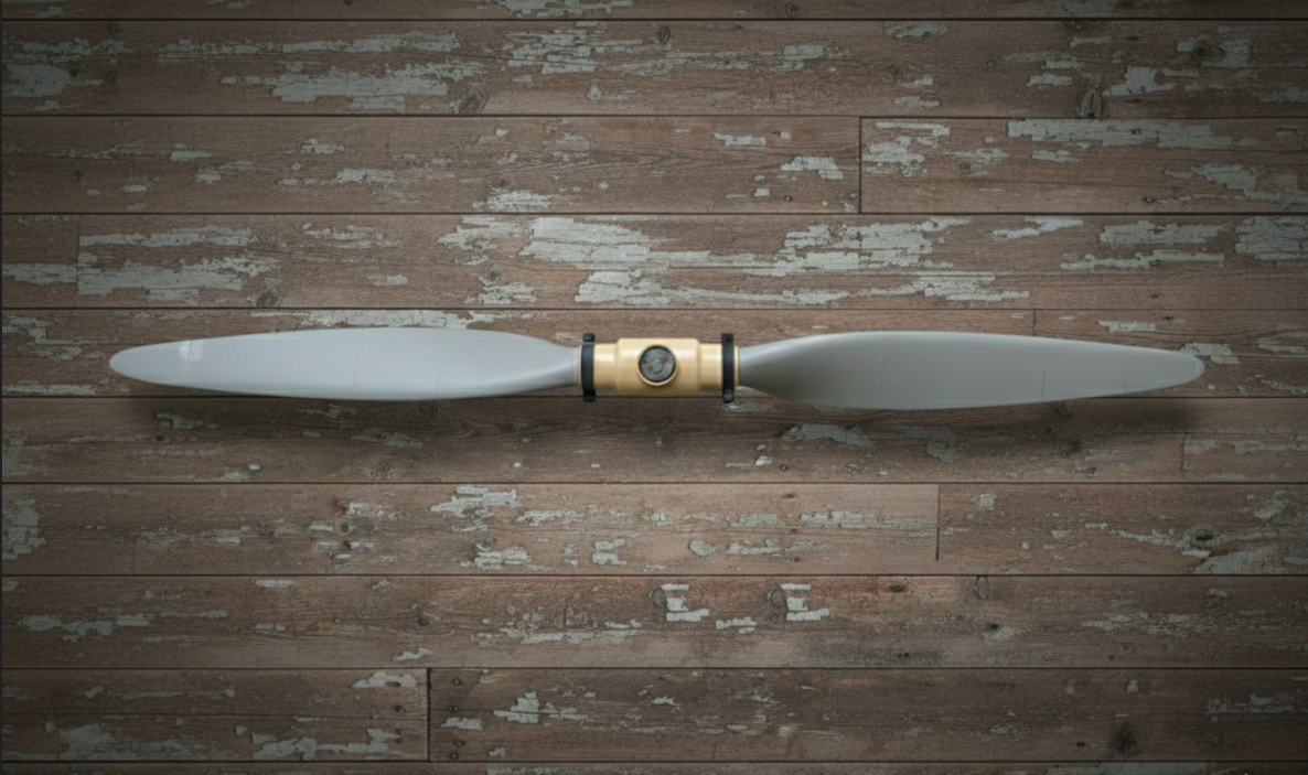
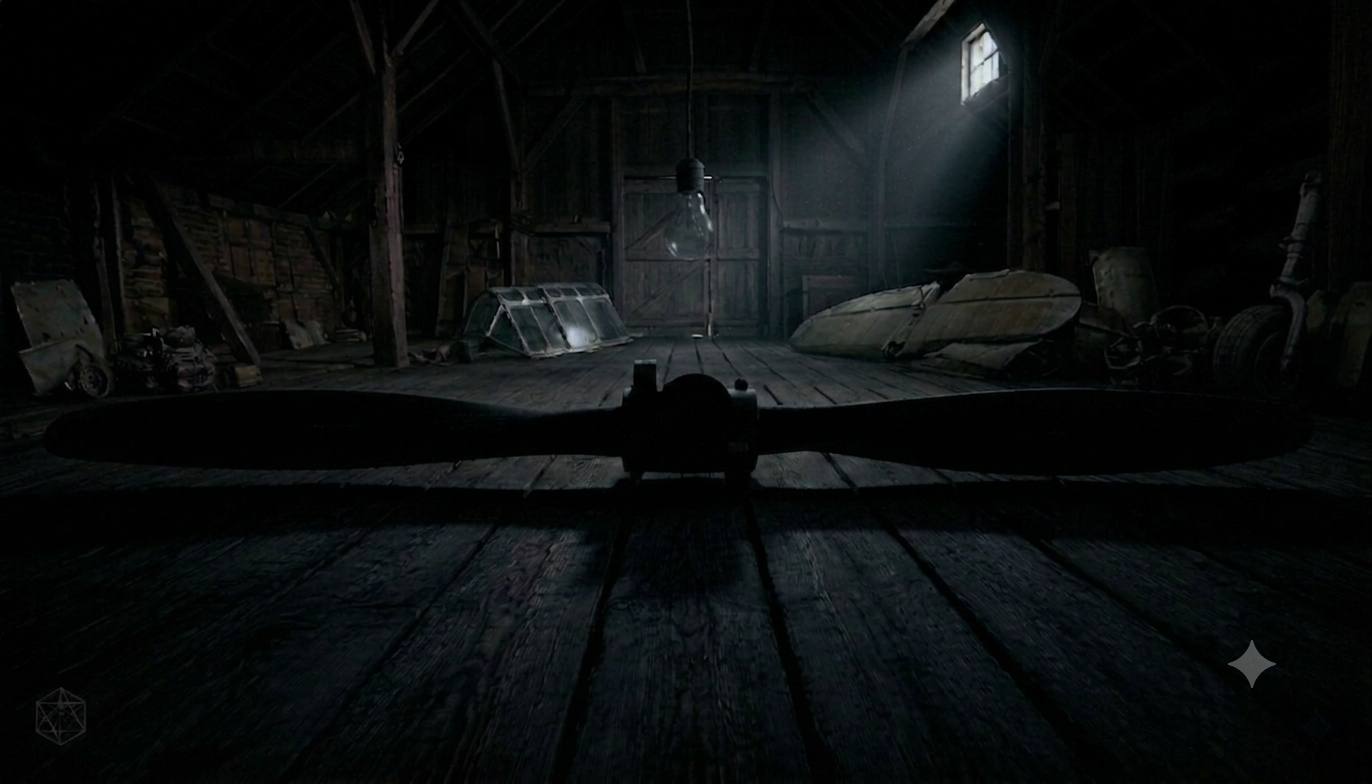
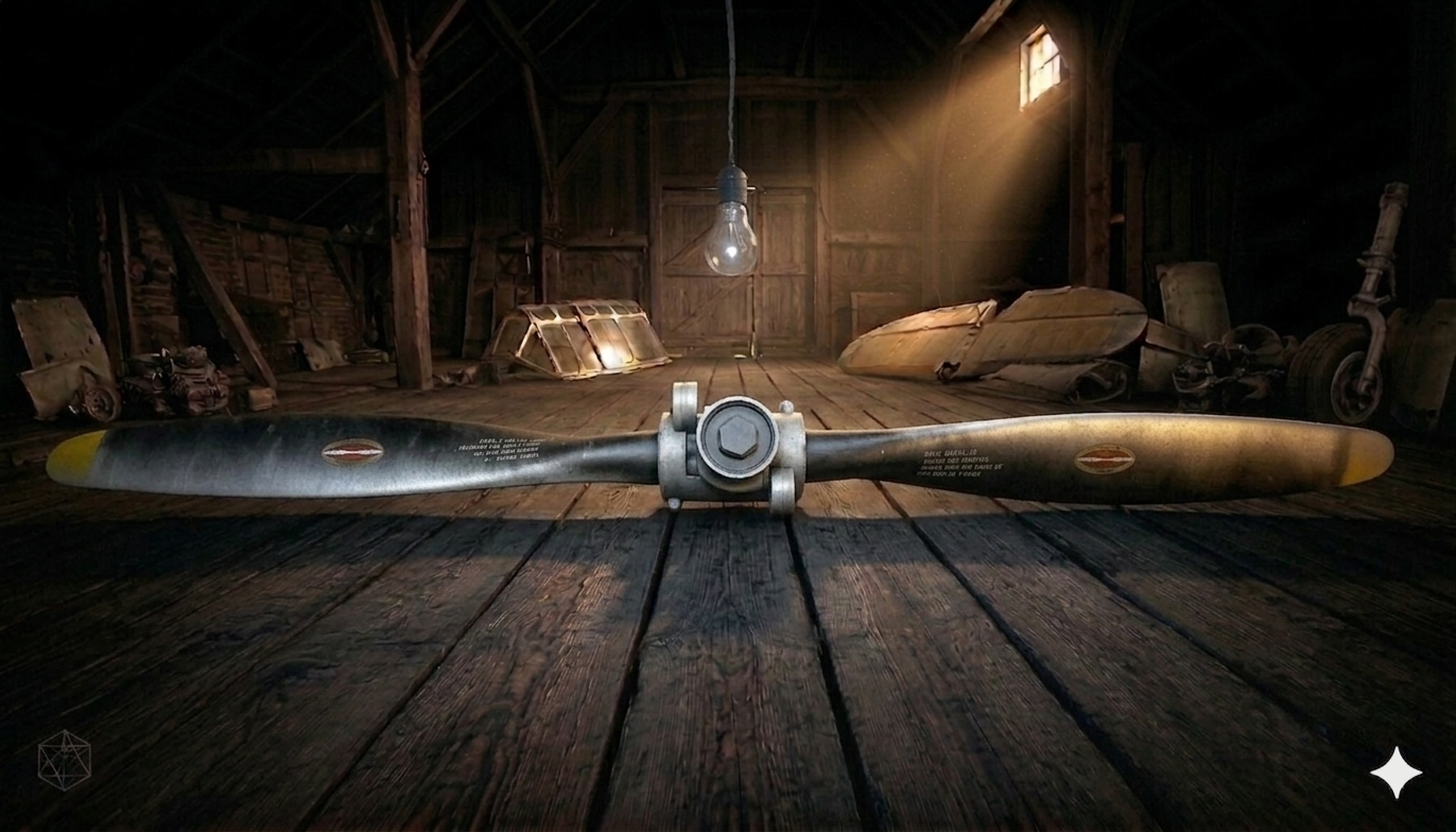
historic propellers replicas, without compromises on scale,
without guesswork on history. Right from your
desktop 3D printer.
(So Far...)
Each model that ends up in our catalogue represents an actual specific propeller type — a real part, from a real aircraft, from a real era. Not interpreted, not approximated.
We work from surviving original manufacturer drawings, maintenance manuals, and actual measurements. The result is a file set you can print, assemble, and display with the confidence
that what you're looking at is virtually indistinguishable from the real thing.
The Propeller Factory exists to answer one question:
What would it take to produce
an honest, dimensionally accurate replica of a historic aircraft propeller?
Vintage aircraft propellers are remarkable artefacts.
They shaped the look and sound of an era that defined modern aviation.
They are also large, heavy, expensive and increasingly rare to find in original,
unmolested form, much less as a complete unit. Museums have them. A handful of
collectors have them. Everyone else does not.
The question was then whether desktop 3D printing in its current form — accessible, affordable, and surprisingly capable — could close that gap. Not by producing something that gestures at the real thing, but by producing something that, dimensionally and structurally, is the real thing.
That meant going back to original engineering drawings, overhaul manuals and every bit of surviving technical information. It meant taking measurements of the genuine article where possible. It meant several complete prototype builds to validate the design, check blade shape and twist and get blade joint geometry right and tight.
Every model begins with locating primary sources: Original blade drawings, overhaul manuals, station-by-station chord, profile type and thickness data. Where sources conflict, the standard is to err toward the most commonly referenced specification and period-correct design principles.
No dimension is estimated if primary sources exist. Any deviation is made only to improve printability or avoid unnecessary complexity.
We test-print and assemble every part of every model several times before release, as geometry that looks correct in a render can still fail when printed.
All parts are designed and sectioned to fit a 3D printer with a min. 210 mm cube build volume. You do not need the latest 3D printer, nor do you require exotic hardware. Expect around 120 hours of total print time and +/-5 kg of filament to go into this project.
Basic PLA handles 95%+ of the model. It is cheap, easy to print and prints dimensionally accurate. For the thinner outer blade sections — where edge lifting is of concern — consider upgrading to PLA+ or PLA-CF.
Every part has a recommended print orientation for strength and surface quality. Gyroid infill is recommended throughout. Four walls minimum and 'snug' type standard supporting where needed.
A four foot (1.3m) blade is typically split into seven sections for printing. Thin trailing edges will want to lift. Slow the outer wall to 50 mm/s, add a brim, enclose the printer if you can. Print two or three sections side-by-side as proximity of parts on the build plate helps to keep temperatures stable, reducing potential for warping.
Most hub parts are printed upright, with standard settings, but inherently require a decent number of walls to ensure strength. Where the real propeller uses aviation grade bolts, the model uses off-the-shelf fasteners that are dressed up with a 3D printed jacket to look like aviation-grade hardware, markings, castle nuts and all.
The propeller is typically made up of two main sub-assemblies: the hub and the blades, both built separately and joined in the final step. Required: Slow-cure epoxy for glue-up, a handful of fasteners, and patience.
The hub is the propeller's structural core — glued and bolted through with M8 OR 5/16th size fasteners. The hub typically assembled from sections into two halves, then bolted together. In the case of a pitch-change mechanism, this is reproduced as a functional feature.
The blades are divided into printable sections, which are combined using tongue-and-groove type joints, reinforced with M8 or 5/16th and M4 or 5/32nd threaded rods running through the spine. Assemble vertically. Apply slow-cure 2-part epoxy — 30 to 90-minute working time is essential. No superglue. No 5-minute epoxy.
Not all printers show the same level of accuracy. Test-fit every joint before committing to glue. The fit should be snug — tight enough to hold, loose enough for excess epoxy to escape. Sand mating faces with 80-grit beforehand.
This is where the scale of the full assembly becomes clear. This step closely replicates the assembly process and sequence of the actual propeller. As it should.
Use slow-curing 2-part epoxy with a minimum 30-minute working time. Cyanoacrylate and 5-minute epoxy are not strong enough and will leave you short on working time mid-session.
The assembly is done. Now you make it look like it dates back to when it was originally flown -or- like it just came out of the factory. Either way: Attention to detail is the key point.
Even though glue squeeze-out is likely to fill any gaps, automotive body filler is used on the seams, followed by rough sanding, then spray filler. Keep sanding until the 'washboard' sound quiets down when sanding manually. Feather outward from the seams until you have covered the full blade length. Work up through the grits to 400 before applying primer. Apply light pressure only!
Classic wartime scheme: graphite black blades, insignia yellow tips, grey barrel with bare-metal accents -or- push further and go for the polished aluminium look: chrome effect paint or automotive vinyl wrap on the blades. Either way, surface prep is everything.
3D-printable stencils for the blade markings are included (drawing number, serial number), or you can make your own. Hamilton Standard PD-039 decals go mid-span, one each side, one right-way-up and one inverted. That's exactly how it was done.
Worn paint on the leading edge, heavier toward the tip. Oil and grease seepage at hub seams. Dry brushing with dark tints. The leading edge is what takes the punishment in service — treat it accordingly. Decals and stencils are always applied before weathering.
Graphite powder is used on all PLA-on-PLA sliding surfaces — applied only AFTER painting. No grease, no oil, no Teflon spray. The completed assembly hangs off a single M10 × 140 mm hanger bolt and once it does, it is time to step back... and admire your work.

Questions about a model, a build, or the research behind it? We're always happy to hear from you!